Pulling tubing to change dimensions is nothing new, but pulling using a tightly controlled dynamic mandrel is a unique technique that can impart a wide range of wall thicknesses.
Editor’s note: This article describes a specific tube drawing process. For an introduction to drawing, see Tube Drawing Principles.
Drawing tubes on a drawbench is nothing new. Whether the bench uses a chain-pulled carriage or uses a hydraulic system to operate the draw carriage, the process can change the OD, ID, and wall thickness of the tubing. Drawing can also improve surface finish and even improve grain structure.
Subduction, the simplest drawing process, can reduce OD and ID and change wall thickness, depending on the die design and tube D/t ratio. The equipment operator uses a pointing process to reduce the outer diameter of one end of the tube, then thread the pointed end through the die. From there, the draw bench does the rest, running the entire length of the tube through the die.
Another drawing process, rod drawing, uses a rod (or mandrel) that supports IDs along the length of the tube.
said Paul Russo, president and co-owner of George A. Mitchell Co. Other common drawing processes use fixed mandrels. A mandrel, also called a mandrel plug, is inserted inside the pointed tube and advanced until it approaches the die bearing, where it sits in a rest position at the start of the draw.
While these processes are more than adequate for many drawing applications, engineers at George A. Mitchell Co. have found ways to devise variations of the traditional drawing process. This innovative process involves moving the mandrel to change the ID as the tube is being pulled.
Many products, whether plate, sheet, pipe, tube or profile, are made from materials of constant wall thickness, but many also benefit from having varying wall thicknesses. receive. Using the lightest material for most of the product and using heavier material only where it is needed (strength, welding to another workpiece, threading, or other design features) reduces material consumption and product weight. is optimized.
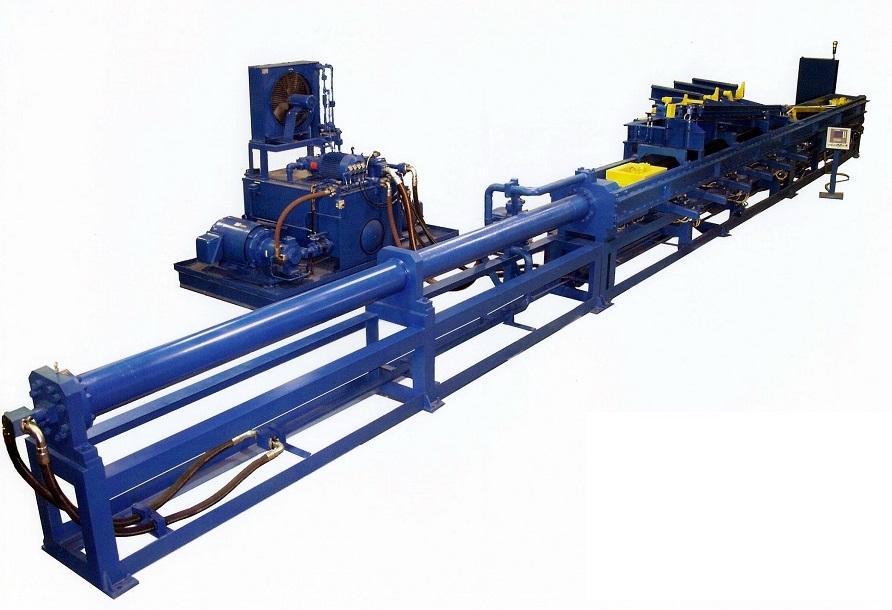
To change the tube’s ID, Mitchell’s engineers came up with a mandrel of mandrel rods programmed for dynamic motion. The dies have include angles and straight bearings, and the mandrels have a precisely engineered taper. The movement of the mandrel is precisely controlled during the drawing process, resulting in tubes customized for their application, i.e. tubes of various wall thicknesses.
“Moving mandrels is nothing new,” Russo said. “Mandrel static position control (e.g. to compensate for wear) has long been done via mandrel screw adjusters.”
Attracted to vehicle applications
The technology has potential for countless applications, but Mitchell’s staff found the most use in the automotive industry.

Pulling tubing to change dimensions is nothing new, but pulling using a tightly controlled dynamic mandrel is a unique technique that can impart a wide range of wall thicknesses.
“Many sports cars have aluminum tubular drive shafts,” says Russo. “Removing weight along the length of the tube helps reduce vehicle weight. This technology allows thicker ends where strength is needed to attach to the transmission and differential.” He said.
Using thin-walled aluminum tubing for drive shafts might sound like a recipe for disaster, especially given the torque commonly produced by high-performance cars, but it’s not.
“Stiffness comes from wall diameter much more than wall thickness,” Russo said. “In the calculation of stiffness, the diameter he is raised to the 4th power.”
At least one automotive crash tip design uses drawn tubes with varying wall thicknesses. Crash chips, also known as crash boxes, are located between the bumper and chassis to absorb some of the energy of the impact and limit its transmission to the passenger compartment. It’s like a shock absorber that only works once.
The Crush Tip is progressively compressed, crumpling the thinnest section first, providing a gradual and progressive resistance to impact. As thicker areas are compressed, they absorb progressively more energy. Although the impact is sudden, this kind of crush tip compresses relatively slowly.
The idea behind the design of this crash chip is somewhat sophisticated, but the technology makes the solution simple and elegant. And it arguably provides better impact protection than crash chips with similar properties.
The bike design also benefits greatly from this variety of specially crafted variable-wall tubes. “Some composite bike frames are weighed in ounces,” says Russo. “Steel frames aren’t that light, but the technology helps.” Many high-performance mountain bikes are made of his AISI 4130, also known as chromoly. This is ideal for racing and other applications that require strength while being lightweight. Aircraft quality medium carbon low alloy steel with chromium and molybdenum for strength. Reinforced ends allow welded joints with other tubes.
beyond manufacturing
Applications for this technology extend beyond manufacturing to the search for valuable ores, gemstones, oil and natural gas. “These tubes are thin-walled along the length and have thicker walls at the ends for ID and OD threading,” he said Russo.
“Some of the pipes made this way had to go to the lab. [drilling] It’s a secluded place by its nature,” Russo said. In fact, it was so remote that some materials, such as drill he tubes, were transported by helicopter.
“By making these tubes as light as possible, the transportation step will be more efficient,” Russo said. A small amount of fuel is required every hour to fly a helicopter. A lighter tube means more in one trip.

Pulling tubing to change dimensions is nothing new, but pulling using a tightly controlled dynamic mandrel is a unique technique that can impart a wide range of wall thicknesses.
Variable-wall tubes can be long (the longest known to Russo is 33 feet), giving part designers almost all the freedom traditional drawing processes afford. The dynamic mandrel drawing system can give circular or elliptical IDs, but there is one caveat. IDs must be symmetrical on both the X and Y axes. Beyond these parameters, the possibilities for other applications are endless.
“Imagination is the limit,” said Russo.

